Burlington
& Missouri River Railroad
An HO Scale Model
Railroad by David Lotz
|
Burlington
& Missouri River Railroad |
St. Louis Layout Construction Photos
Looking back, I wish I had taken more photographs of the construction of the layout. But when you are under a self-imposed deadline, the priorities aren't pictures!
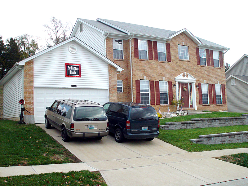 |
This was our family's St. Louis (Oakville) home for eight years after EDS moved us from Iowa to Colorado and then to Oakville. Two more moves were in our future, but for now, this was to be the first home of the B&MRR. The layout design was first created in 1985 for our house in rural Madison County Iowa. After the move to Colorado Springs, it was modified for the basement there, but it wasn't until we moved to Oakville in 1998, that serious thoughts of construction could actually he had. With the incentive of the NMRA National Meet coming to St. Louis in July of 2001, a small band of serious model railroaders (the No-Name Round Robin group) began construction of the B&MRR in January 2000, along with two other start-from-scratch layouts and adding finishing touches to two others. My thanks to my dedicated friends; John Lee, Richard Schumacher, Richard & Venita Lake, Tom Engle, Ken Thompson, Randy Meyer, John Schindler and Hank Kraichley as well as to my wonderful, encouraging wife Diana and my sons, Joshua, Jacob and Joel, who also added their special touches. |

| January 28, 2000 - Construction has begun!!! The Southeast corner of the basement and the beginning framing for the Galesburg Staging yard. The framework for most of the layout is completely stand-alone, not attached to the exterior walls. |
 |
January 28, 2000 - Looking along the East wall showing the framing for Galesburg Staging. Here you can see the 2x4 back framing was installed flat to the wall to conserve space in the narrow aisle between the exterior wall and the Dispatcher's Office wall. February 28, 2000 - Erected the south wall frames and completed the
supports for the Creston Staging Yard. |
 |
March 24, 2000 - With the
uprights completed along the South wall, we began the helix section.
I'll never forget the confused looks at our first round-robin meeting when I tried to
explain the many functions this footprint would serve! It provides for double-track reversing loops for both levels, it contains the helix, but it also has the West Burlington Hill mainline wrapping around the helix until it meets it at one point, takes one loop around with the helix and then continues up the south wall to West Burlington. The curved fascia on this section is 3/4" plywood with no grooves cut into the back side. Needless to say, there was some trepidation among the crew members that the screws and glue would hold this in place. It did. |
 |
April 14, 2000 - This view shows the first loop of the helix completed. The helix was originally designed as a circular helix, however, once construction began on the helix deck, we noticed the tracks were going to pass directly in front of, and would block access to the stand-pipe cleanout. A slight modification, making the helix oval shaped, allowed the tracks to pass behind the stand-pipe and resulted in a less-demanding grade on the helix and the West Burlington Hill. In the background you can see the supports are ready for the Creston Staging yard decking and the Galesburg backdrop has been installed. |
 |
The track arrived on April 19th and the cork roadbed arrived two days later. This photo was taken on April 23, 2000 as we were experimenting with Galesburg's East yard throat's trackage. This view shows the connection between the staging yards and the helix. |
 |
April 23, 2000 - Before permanently attaching cork roadbed and track, it is important to "test fit" the trackage to make sure that your paper plans will work in the physical realm. To the right are the two mainline tracks with the seven staging tracks to the left. This shot also provides a good view of the supports for the Creston staging yard. |
 |
January 1, 2001 - Here we skip forward showing significant progress has been made the previous year. Since I had been so focused on construction, I had forgotten to take progress photos. So on this New Year's day, I took a complete series of photos showing the whole layout as of this day. The Galesburg and Creston staging tracks are laid, the Galesburg coaling tower is in place and the Creston CO-OP elevator is being tested around the water pipe. The Digitrax DCS100 is temporarily attached to run test trains - the primary test train sits to it's right. This is the "problem" train, a U-Boat that always gave problems on the modular layout in Colorado, an 86-foot auto box car not weighted to NMRA standards, coupled to a 50-foot boxcar with mismatched trucks and bringing up the markers, an intermodal well car with a top-heavy load. |
 |
It took nearly four months to complete the helix section. This view clearly shows the multi-functional aspects of this area. Around the perimeter of the helix is the double-track mainline of the West Burlington HiIl and on the top and bottom levels you can see the entrances and exits to the reversing loops for both levels. |
 |
On this side of the helix section, you can see how the mainline shares one loop of the helix to gain enough elevation to continue up the south wall to West Burlington. |
 |
At this point in time, we have the framework in place in the southeast corner of the room. The upper level decking stops just above the Central Avenue section. |
 |
Continuing around the layout, this is the section with both the start and the end of the grade for the West Burlington Hill. The lower area is where the 6th Street bridge will be located, and above will be the West Burlington Avenue overpass. To the left shows the bridging section transitioning from the framework against the walls to the Burlington & West Burlington section. This section allows crawl-through access for the open side of the Shops. |
 |
The next three photos show the Burlington (lower) and West Burlington (upper) section's cantilevered framework. This view also shows the duck-under for access to the back of the Shop building on the upper deck and to trackage that cannot be reached from the front of the layout. The plans are for building the south half of the building, with the portion facing the wall to be open. A pair of large mirrors mounted on the wall will provide a view into the inside of the shop building, where locomotives will be displayed in various stages of repair. |
 |
By using the cantilever design, we have provided a very wide deck for the Burlington yard and also enough room for the West Burlington Shop Building. The upper deck supports are 3/8" plywood gussets, glued and screwed to a 1x2 slightly raised above the edges of the plywood. This design is amazingly strong! |
 |
This shot is also of Burlington and West Burlington and shows just how wide the decking is. |
 |
Here, looking north towards the northeast corner of the room, you can see that progress has been made on the upright framing along the east wall, and we are working out the design for the framing for the Mississippi River bridge and Dayman section of the layout. |
 |
Here, looking east towards the northeast corner of the room, you can see the Illinois framing in place, with a huge gap for the river section. |
 |
The final construction shot is from the middle of the river looking towards the northwest corner of the room. The Illinois framing is partially finished - the cantilevered upper arms are yet to be installed, the back uprights where they will attach can be seen to the right. The small gap between the two uprights on the lower level will contain the trackage for the K-line/Carthage Branch. The north ends of the staging yards is in the background. |